Since I began this blog it has focused on preservation of the AY-3-8500 "Pong on a chip" circuit (with one exception.) As has been said before, the tools and experience developed to emulate the AY-3-8500 can be used on other discrete circuits from the time period. The AY-3-8606 "Wipeout" game has now been simulated using said tools and experience, just like the '8500 was in August, and it took under two months to do so. This post describes the work done so far, and also documents some of its internals.
How to emulate discrete integrated circuits
I've talked about the process involved in past posts, here are the steps laid out again.
1. Obtain circuit specimens
2. Decap, photograph, and stitch images
3. Highlight images
4. Process images and correct errors
5. Simulate circuit in JavaScript, correct more errors
6. Run DLAET to abstract netlist into Verilog
7. Port to FPGA
8. Use Verilator to emulate circuit in MAME
At this moment, the AY-3-8606 is at step 5 and the AY-3-8500 is currently pioneering step 7. Thanks to Sean Riddle for undertaking steps one and two, which resulted in the images below. Note: All die photos on this post come from Sean Riddle under CC-BY-4.0.
You can check out the JavaScript simulation here. The simulation is purely for debugging purposes, so I haven't made much of an effort to make it user friendly. The files involved with the process are available here.
First impressions
The AY-3-8606 was part of General Instruments 86XX "economy" game system circuits. Like the earlier AY-3-8500, GI sold these chips to anyone wanting to build and sell systems using them. Many almost identical consoles were produced using the schematics and screenshots found in the catalog (page 460), these are now referred to as PC50x systems. The console contains the support circuitry, controls, color chip, modulator, speaker, etc while the interchangeable cartridges contain the unique game chips.
 | ||
| A standard PC50x system (pong-story) |
The PC506 game carts went by "Wipeout", "Wipe-off", "Destruction Game", "Brix Game", or "Jeux de destruction" and contained an AY-3-8606 with it's pins mapped to the cartridge connector. 10 game variants, some two-player, can be selected using the console's buttons. Additionally, three switches could adjust the bat size, ball size, and speed of the game. Below is a table comparing it to the earlier AY-3-8500. It's a bit more complex, but not by much.
| AY-3-8500 (NTSC) | AY-3-8606 (NTSC) | |
| Transistors | 2318 | 2975 |
| Nodes | 973 | 1633 |
| Polygons | 10292 | 12435 |
| Input clock | ~2Mhz | 3.579545Mhz |
 | ||||
| The AY-3-8606's surface. |


 Above is an image of the decapped chip's surface. There are a few noteworthy features immediately visible. Three wafer
test circuits are present on the edges of the die. The text "©
1978 G.I. CORP." fills an empty spot in the upper-left. Nearby that is a collection of
numbers written using different layers. Lastly "80-80395" appears in the
bottom-right. None of these features affect the game logic, so
highlighting them isn't necessary.
Above is an image of the decapped chip's surface. There are a few noteworthy features immediately visible. Three wafer
test circuits are present on the edges of the die. The text "©
1978 G.I. CORP." fills an empty spot in the upper-left. Nearby that is a collection of
numbers written using different layers. Lastly "80-80395" appears in the
bottom-right. None of these features affect the game logic, so
highlighting them isn't necessary.There is a repeating structure near the bottom right. This stores the state of the blocks inside six shift registers, corresponding to six rows of blocks. Interestingly, there are 10 segments per shift register, but only 8 blocks per row. More on this later.
Fixing errors
 |
| A high resolution look |
 |
| The generated image, along with the datasheet's rendering of game #9 |
It works! ...but not correctly. It looked like game #9 from the catalog, except some of the bricks were on the wrong side, the scores were vertical lines, and the bricks overlapped the top bounds. Time for more debugging!
Unlike some other chips, PC50x series games use strobed signals to read up to 10 different game select buttons with only 7 pins. It seemed that without external buttons the circuitry was changing to game #10 partway through a screen, explaining the misplaced bricks. I wrote a little code to simulate the external buttons via a checkbox, which fixed this issue. Because of this strobing the 8606 will probably exhibit odd behavior whenever multiple buttons are pressed, I haven't experimented with it though.
After selecting one of the other games, I saw that 9 columns of blocks appeared instead of 8! A close look at the shift registers revealed that they held 10 columns of blocks. The 10th column, which is off the right side of the playfield, is always reset to empty. The 5th column (middle) is reset to empty/full based on the game selection logic.
Take a look at this captured footage (skip to 4:14.) In game #9 the wall appears to be 9 layers thick (this confirms the catalog's screenshot.) So at least one game mode uses the middle column. It turns out that activating the reset pin (which the simulation does before loading) can only reset the blocks when the scanline is in a certain region. If you turn it on for longer it will correctly reset the blocks. This means that switching from game #9 to another one without hitting reset will leave blocks in the middle column, doing the opposite will create a gap in the middle of the wall. Also, the footage seems to suggest that the blocks do overlap the top boundary in real hardware. I don't have a physical console to confirm that this is the case, but the fact that little details like these are preserved is pretty impressive in terms of emulation accuracy.
 |
| This was causing the vertical lines. Can you see what's wrong? |
 |
| Game 7 |
Looking at the circuits
I've explained some of the AY-3-8500's circuitry in great detail. My current focus is emulation, so I won't do the same thing for the AY-3-8606. Here's a short overview of different components based on what I learned while debugging it.

Next to the clock divider + driver is the horizontal and vertical control signals, just like in the AY-3-8500. The shift register is a little smaller though. All of the shift registers in the 8606 are more compact because they use capacitor-capacitor segments, unlike the AY-3-8500 which uses mostly capacitor-latch segments.
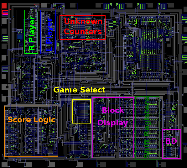
To the left of that is another horizontal+vertical counter pair. What this one does is a mystery to me, although I''m guessing it's part of the ball circuitry. Past those are the two paddle counters, one for each player.
In the lower-left is the score counter/display logic. It seems almost identical to the score areas on the 8600 and 8605 die photos. Another area of interest is the center where a game select PLA resides.
Next Up
You can contribute by highlighting! It's visual identification, not necessarily hard, it just takes a lot of time. The AY-3-8606 took over a month to highlight, while processing and error hunting took less than a week. Highlighting doesn't require much focus, so I worked on it whenever I needed to listen to something else. Shout-out to all the people who let me work on a laptop wherever one does not usually work on a laptop, you are preserving games you never even heard of!
What chips are next? plgDavid of the MAME team is sending off some chips to be decapped. He has the PAL variants of the 8603 (road race), 8607 (light gun games), and 8610 (improved 8600.) Hopefully useful die shots will show up sometime soon. If you have circuit specimens or the consoles that contain them (nonfunctional included) and wish to donate, I'll help with finding someone to decap them. I'm particularly eager to get die shots of Atari's chips, and the ones in Nintendo's Color-TV game series.
In the meantime, there are four existing die photos I'm looking at for emulation. First up is the 8600 (NTSC variant) which is pretty much an upgraded AY-3-8500 with more games and bidirectional movement. Second is the 8605 (PAL variant) submarine/warfare chip. Third is the MM57105, National Semiconductor's competitor to the AY-3-8500. It could play its games in COLOR (without a support chip.)
 |
| Die surface of the TMC0280 |
The last game chip to have been decapped as of 3/2019 is the MPS-7600, from the Coleco Telstar Arcade cart #1. I'm not doing this one anytime soon due to lack of any documentation, and also because its much more complex than what I've done so far (it has a custom microcontroller inside.) The fourth chip I'm thinking of emulating is the TMC0280. Never heard of it? How about the Speak & Spell? The TMC0280 is the voice decompression/synthesis engine inside it. It has a lot of transistors, but many of those are part of repeating arrays.
So which one to work on next? Comment below if you have a preference, or try highlighting one yourself. I'm leaning towards the AY-3-8605 because its a fairly unique game.
Two other things: first, I'm in the process of setting up a Patreon account for anyone wanting to contribute monetarily (all files and posts will still be public.) EDIT: here it is! Second, I'm going to be giving a talk at Latchup conference in Portland (Oregon) come May. Stop by if you're one of the 0.0086% of people around there. Anyway, my next post should be on the current/future progress of FPGA porting, so stay tuned (to channel 3 or 4. ;)
 |
| I ran the simulation for 10 million cycles while writing this (~1.4 seconds) The ball clearly moves, bounces and destroys blocks. (There was an error in the score logic) |
Hey listen, I'm just a MAME project coordinator and not one of our hardcore reverse-engineers but based on your description I am not certain that your "6. Run DLAET to abstract netlist into Verilog", "7. Port to FPGA", "8. Use Verilator to emulate circuit in MAME" workflow is going to be accepted into MAME proper. Maybe in a fork or something. I could be wrong of course.
ReplyDeleteBut here's what I'm thinking:
These days MAME has its own netlist subsystem, mainly designed by software engineer and MAMEdev member "couriersud". Most of our resources so far are behind supporting it.
It is possible MAME's netlist subsystem is not fully fleshed out enough to do a logic-level emulation of any of the chips you're targeting.
Still, full PCB games like Atari's Pong, Breakout, Rebound, have all used MAME's netlist system and used it successfully, and I believe we're wanting most TTL-level emulation to take that route.
By all means, we could use people with your talent in decapping and reverse-engineering, and regardless of your workflow we'll find a way to use your notes here from your blog OR if you submit something. But if you plan to eventually submit, my only suggestion is to take a closer look at MAME's own netlist subsystem for your purposes.
But perhaps there's something I'm not understanding about what you intend to do.
Hi Stiletto
DeleteI haven't explored MAME's netlist system in-depth but it's somewhat like DICE's or SPICE's, that is a priority queue of changing signals. This makes for very accurate emulation, but requires a decent amount of processing power. I don't know about MAME drivers, but the more complex games supported by DICE struggle to maintain full speed (even with DICE's optimizations.) The goal of DLAET was to simplify the netlist and replace the queue system with a pair of specialized .cpp and .h files. This should make it muuuuuch faster with minimal accuracy reduction, as long as any tricks involving timing and whatnot are accounted for.
Each approach does have pros & cons, and analog components still have to be done the normal way. For TTL arcade board emulation you could debate the merits of each, as well as have a faster but possibly less accurate fork for lighter systems. Something like that happened when discrete sound samples were replaced.
When you use the netlist approach on the inside of a chip, its a whole different story. The function of a few dozen TTL chips is reproduced with hundreds or even thousands of transistors, so netlist simulation would be extremely slow (<5% realtime.) Maybe given 20 years of Moore's Law it would be feasible, but for now simplification and Verilator have to be used.
AY-3-8605 is really the most interesting, second is:
ReplyDeleteAY-3-8700/AY-3-8710 tank battle
3° AY-3-8603 roadrace
4° AY-3-8760/AY-3-8765 stunt cycle
5° AY-3-8604
...in my opinion
Ótimo trabalho, impressionante! Estou ansioso para quando for um executável jogável. Me pergunto se não seria possível transcrever os processos do chip para linhas de comando.
ReplyDeleteThis comment has been removed by a blog administrator.
ReplyDeleteWoo-hoo! My first spam!
DeleteI tried to build a project under uno
ReplyDeleteSomething even happened
https://s.micp.ru/3w3ws.jpg
The code is exactly correct ay38500NTSC ?
especially embarrassed that the numbers under each other are
and the second question - how is the control connected?
Variable resistors? What conclusions?
It would be nice to do on the buttons, up / down.
Then you can use the keyboard or joystick.
Well, if I fail, then I will wait for the release for the mister, I also have it :)